Three-Limb Core: The Workhorse of Three-Phase Transformers — and Why It Matters for Your Order
Three-limb core is the default structure for three-phase transformers up to ~30–50 MVA — compact and material-efficient. Hidden constraint: no zero-sequence flux return → must pair with a delta winding (Dyn11). Five-limb wins on Yy groups and shipping height. How to choose, and what to specify.
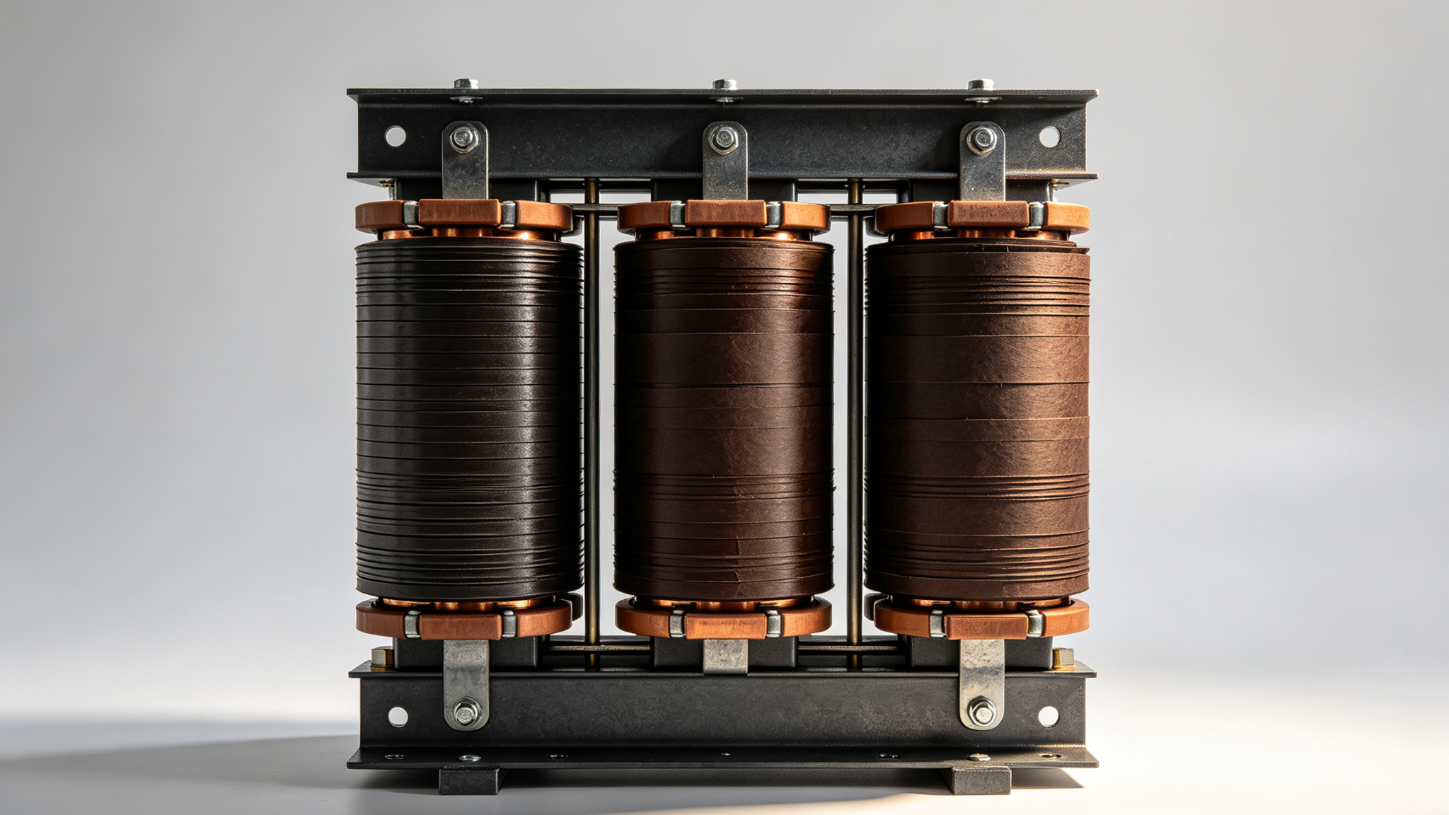
Introduction: The Shape You See in Almost Every Transformer If you walk through a substation, a factory electrical room, or a wind turbine nacelle, the transformer you see most often has the same silhouette: three vertical legs connected top and bottom by horizontal yokes. In the industry, this is called a three-limb core (also “three-leg,” “3-leg,” or “core-type”).
It is not the only way to build a three-phase transformer. The other common structure is the five-limb core, with two additional outer limbs that have no windings — they exist purely to provide a magnetic return path. There are also shell-type, multi-limb, and three-single-phase designs, but those are specialized.
For the overwhelming majority of three-phase transformers up to roughly 30–50 MVA — every distribution transformer, every pad-mount, most industrial and renewable step-ups — the three-limb core is what you will receive. Understanding why, and where its limits are, helps you specify and source better.
- Why Three Limbs? The Physics of Sharing One Magnetic Circuit In a single-phase transformer, you need at least two limbs (or one limb with a return yoke) to complete the magnetic circuit. For three-phase, you have two fundamental ways to build that magnetic circuit:
Independent magnetic circuits: three separate single-phase cores, each with its own pair of limbs. No magnetic coupling between phases. Heavier, more material, used in very large EHV transformers where each phase is built and shipped separately.
Common (shared) magnetic circuit: three limbs joined at top and bottom by common yokes. This is what the three-limb core does — the three phase fluxes share the same yokes, which is mechanically and materially efficient. The resulting structure looks like the character “日” (sun), or three “I” shapes joined at top and bottom.
The shared-yoke three-limb arrangement is what the industry uses 90% of the time, because:
1)It uses the least silicon steel for a given kVA rating 2)The structure is mechanically simple — only two yokes to wind, three limbs to stack Manufacturing lines for three-limb cores are standardized globally, with mature tooling and processes 3)It is easy to ship and assemble — the whole core fits in one frame 4)The trade-off is hidden inside the magnetic circuit itself, and it is the reason three-limb transformers have a specific winding rule.
- The Hidden Constraint: Zero-Sequence Flux Has Nowhere to Go In a balanced three-phase system, the phase fluxes in the three limbs sum to zero at every instant — they cancel each other in the common yoke. That is why a shared-magnetic-circuit core works in the first place.
But when the system is unbalanced — most commonly during a line-to-ground fault, or when single-phase loads are unevenly distributed — a zero-sequence flux component appears. In a three-limb core, this zero-sequence flux cannot flow back through the other two limbs (because they are 120° out of phase at fundamental frequency). It must instead find a return path through the air, the tank wall, or any other magnetic structure outside the core.
This makes the zero-sequence impedance of a three-limb core very low — meaning very high fault current flows during a ground fault. That is fine if the system is designed for it, but it can be a problem if the upstream protection cannot break such a high current.
The standard solution, used for over a century, is to connect one of the windings in delta (Δ). The delta winding circulates the zero-sequence currents internally and confines them to the transformer — the outside world sees only the positive- and negative-sequence behavior. This is why almost every three-limb distribution transformer uses Dyn11 (delta primary, wye secondary with neutral brought out) or similar vector groups.
- When Three Limbs Aren’t Enough: The Five-Limb Alternative If a Yy vector group is required — for example, to feed single-phase loads directly off the same transformer — the three-limb core will not work cleanly. The zero-sequence flux needs a return path.
That is where the five-limb core comes in. It has the three main limbs (with windings) plus two additional outer limbs that have no windings. Those two outer limbs provide a low-reluctance return path for zero-sequence flux, allowing the transformer to operate with all windings in wye.
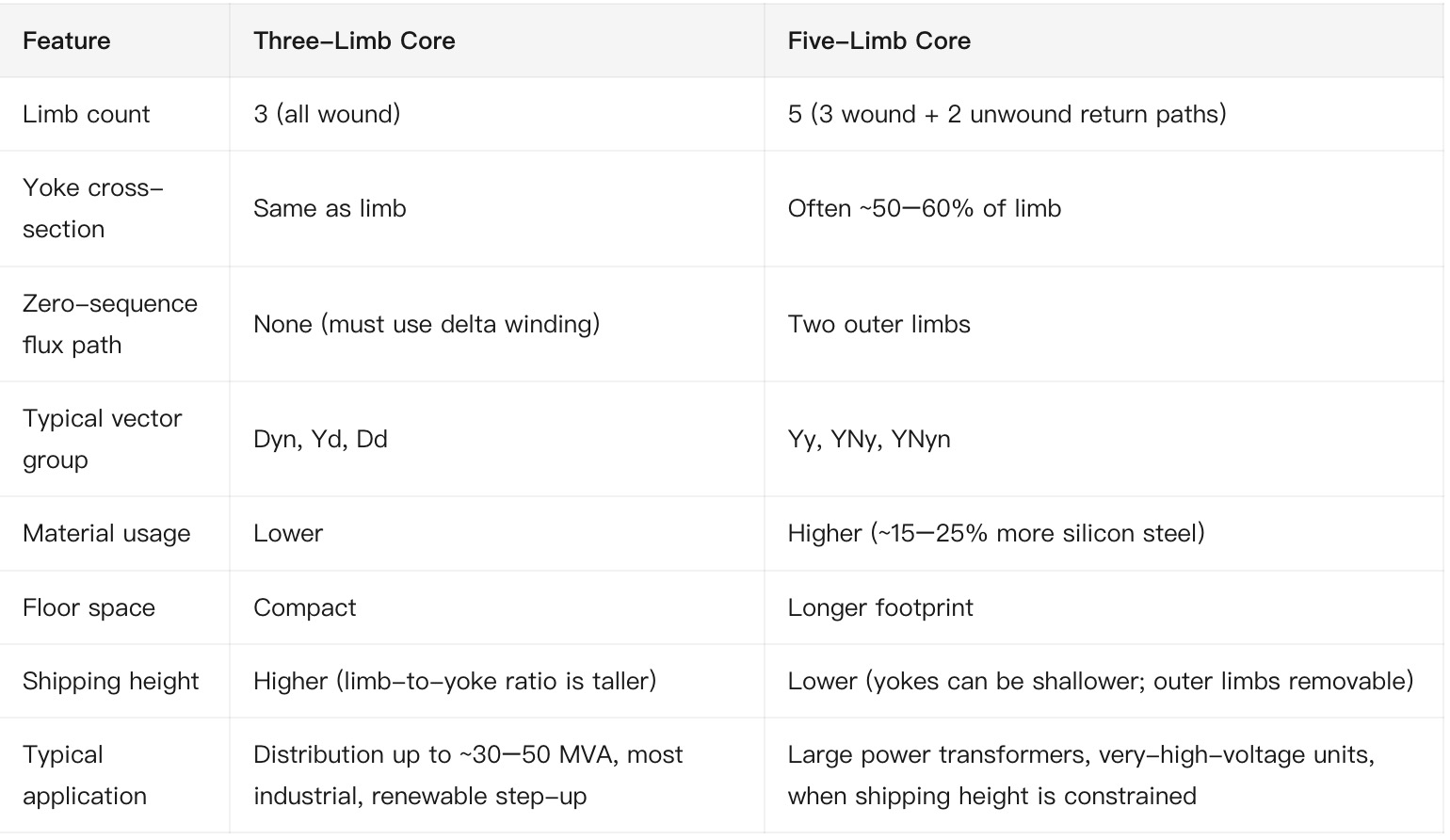 Three-limb VS Five-limb
The five-limb design is essentially the engineering answer to two problems the three-limb cannot solve:
Three-limb VS Five-limb
The five-limb design is essentially the engineering answer to two problems the three-limb cannot solve:
Zero-sequence flux needs a magnetic return path → add two outer limbs. Shipping height is limited (road, rail, tunnel, bridge) → reduce yoke depth and outer limbs. The cost is material, footprint, and a slightly more complex manufacturing process.
- How the Three-Limb Core Is Actually Built For an OEM or buyer who wants to understand what they are getting, the manufacturing process matters because it directly affects losses, noise, and mechanical integrity.
A three-limb core is built from CRGO (cold-rolled grain-oriented) silicon steel laminations, typically 0.23 mm, 0.27 mm, or 0.30 mm thick. The laminations are cut into limb and yoke shapes, with mitred (typically 45°) joints at the limb-yoke corners.
The modern assembly approach is step-lap stacking: each lamination is offset from the one below by a fraction of the lamination width, so that no single air gap spans the full cross-section at any corner joint. Compared to a simple butt-lap joint, step-lap reduces no-load loss by typically 10–30% and significantly lowers noise.
Other critical manufacturing details:
1)Stacking factor — the ratio of steel length to total stack length — should reach 0.95–0.97 for a well-built core. Below 0.95, losses rise sharply. 2)Burr height at the cut edges must stay below ~0.02 mm; higher burrs short-circuit laminations and increase eddy-current loss. 3)Clamping pressure — typically 8–12 MPa — must be uniform. Uneven clamping causes both higher losses and audible noise. 4)Mitered joint gap — should be ≤0.03 mm. Wider gaps mean higher joint loss.
A correctly built three-limb core is mechanically robust, magnetically efficient, and quiet. A poorly built one — bad joints, low stacking factor, uneven clamping — can lose 20–30% more energy as heat and run several decibels louder.
- What to Specify When You Order a Three-Limb Core Transformer If you are sourcing a three-limb core transformer (or buying the core itself as a sub-assembly), the specification sheet should include at least:
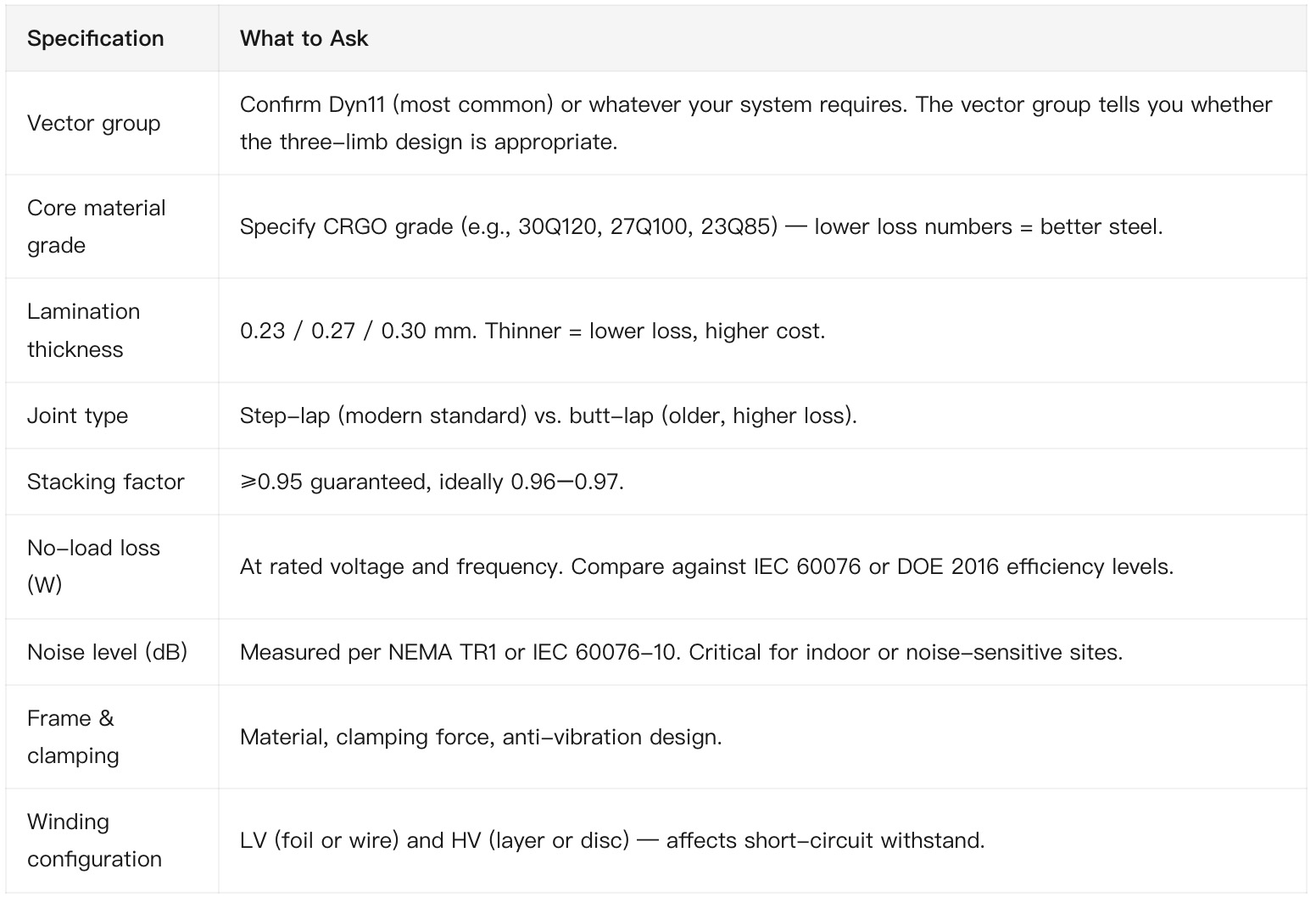 5 questions
For buyers in regions with shipping-height constraints (many road tunnels, container limits, or rail tunnels), ask whether a three-limb or five-limb design better fits your logistics — even if the electrical specification points to a three-limb.
- Common Buyer Mistakes Three mistakes we see repeatedly:
Mistake 1: Specifying a Yy vector group on a three-limb core. It will work in steady-state balanced conditions, but the zero-sequence flux problem during a ground fault will overheat the tank and may trigger protection unnecessarily. If you need Yy, specify a five-limb core.
Mistake 2: Acceptating “industry-standard” stacking factor without confirming. A stacking factor of 0.90–0.92 is technically achievable but translates directly into higher no-load loss. Push for ≥0.95, and ideally ask for the measurement report.
Mistake 3: Choosing the lowest-cost CRGO grade. The difference between 30Q120 and 23Q85 looks small on paper (a 30% loss reduction) but over 25–30 years of operation adds up to a substantial difference in energy cost. For high-utilization transformers, the higher-grade steel pays for itself.
- Conclusion The three-limb core is the default structure for three-phase transformers for a reason: it is the simplest, most material-efficient, and most manufacturable design that works for the vast majority of applications. It has one well-understood limitation — no zero-sequence return path — that the industry has solved with delta-connected windings for over a century.
For buyers, the practical takeaways are:
1)Confirm the vector group matches your system. Three-limb + Dy is the universal combination. 2)Specify CRGO grade, lamination thickness, joint type, and stacking factor on the order. These determine no-load loss and noise. 3)Consider a five-limb core if you need Yy vector group, very-high zero-sequence impedance, or reduced shipping height.
A correctly specified three-limb core transformer, built with proper materials and modern step-lap stacking, will deliver decades of efficient, quiet service. A poorly specified one — wrong vector group, low stacking factor, weak CRGO — will show up in your electricity bill and your maintenance log for the next 30 years.
More from the newsroom

Transformer Insulation Components: The “Quiet” Parts That Decide Your Transformer’s Lifetime
Sep 15, 2026

Transformer Bushings: The Most Critical — and Most Overlooked — Component in Your Power System
Sep 11, 2026

Why Transformer Cores Are Laminated: The Hidden Physics Inside Every Dry-Type Transformer
Sep 9, 2026
Questions about what you just read?
Send your specs or your question — a U.S.-based engineer replies within 24 hours.